The LCGC Blog: Proper GC Column Installation – The Simplest Way to Improve Your Gas Chromatography
The title of this piece may have put you off reading it – in which case you won’t be insulted when I say that even the most experienced gas chromatographers often fail to install columns in the best way possible.
My colleague Dawn Watson likes to use the following quote:
“The beginning is the most important part of the work” – Plato, The Republic.
It’s as true now as it was in 380 BC when it was written, and in analytical terms this often means getting the instrument preparation right.
The title of this piece may have put you off reading it – in which case you won’t be insulted when I say that even the most experienced gas chromatographers often fail to install columns in the best way possible. Even if your column preparation technique is not “catastrophic,” small issues will add to the overall “jitter” of the instrument which may result in sub-optimal performance or even batch failure.
So – for those of you who are willing to learn – let’s discuss the issues related to column installation and learn how to how to properly prepare and install the column into the GC. For all those feeling patronized, please accept my apologies and my admiration for your faultless technique…
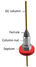
1. Select your column and ferrule. The column phase and dimension selection is covered in other Tech Tips, however ferrule selection is also important. Modern GC columns typically use two types of ferrule – 100% graphite or a mixture of graphite and Vespel (85/15 or 60/40 is typical). 100% graphite ferrules are typically used for most applications using standard detectors such as FID/TCD etc. Graphite/Vespel ferrules are typically used to connect GC columns into MS instruments as they are impervious to oxygen, which is important for MS applications, although they do need to be retightened after the first few thermal cycles to prevent leaks. Metal nuts and ferrules (such as SilTite) can be used for both GC and MS applications and do not need to be retightened but also cannot be reused.
Most manufacturers include the GC column i.d. which is applicable for each different ferrule i.d. – but just in case you are wondering, the table below gives a good guide to ferrule selection;


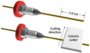
2. The column nut and ferrule should be placed onto the column prior to cutting at the inlet or detector end.
Failure to do so may risk shards of ferrule material entering the column and giving rise to poor peak shape.
Some operators prefer to use a septum to hold the column nut and ferrule in place (to maintain correct column length above the ferrule) during installation.
This should also be done prior to column cutting.


3. Using a scribe (ceramic wafer or diamond tipped pen), score the polyimide coating of the column and, holding firmly just below the score, flick the column above the score away from you.
The wafer has two edges. The smoother edge should be used to score the polyimide coating.
Usually removing 2.0 cm of column is enough to access fresh stationary phase coating at the column tip, although many workers
prefer to take >20cm, especially if the column is being “recovered” due to a loss of efficiency or decline in peak shape quality.


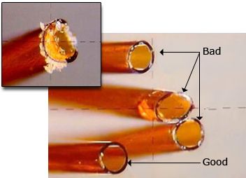
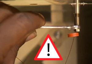
4. Inspect the cut edge with a 10-20X magnifier.
The cut end should be at a 90° angle relative to the tubing wall.
There should be no burrs, shards, or jagged areas.
If necessary, re-cut the column until a proper cut is obtained.
If a good column cut is not made, then significant activity (resulting in poor quantitative precision) and split or tailing peaks may be observed in the chromatogram due to disturbed flow of the sample plug entering the column.


Figure used with permission of Agilent Technologies.
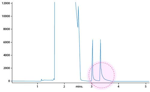
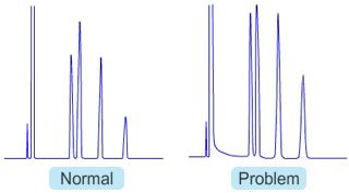
The importance of a proper column cut cannot be over-exaggerated and is the cause of many issues with peak shape, including shouldered, tailing, and split peaks.


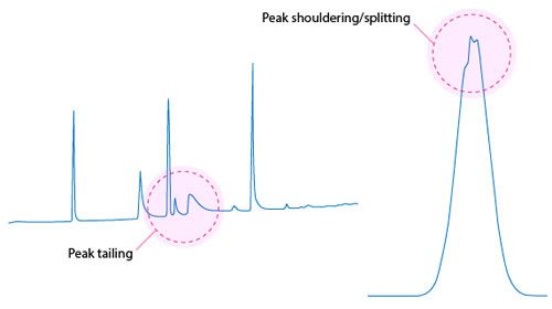
Peak tailing (above) and shouldering/splitting (right) associated with poorly cut columns.
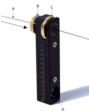
Some workers prefer to use fused silica column cutters of the type shown (right).
1. Insert capillary column (A) in the column cutter as indicated
2. Fix the capillary column by turning the securing disk (B)
3. Cut the column by turning the cutting disk (C), one full rotation is usually sufficient
4. Use the magnifier (D) to verify the cut
Whichever column cutting is used, wipe the column outside surface above the ferrule with acetone or n-hexane to remove finger grease and other residues from the exterior surface of the column.


5. Place the column in the GC Oven making sure the column tubing does not touch any of the internal surfaces of the oven. If the column touches the hot oven wall, the polyimide will “bake out” and become brittle. You risk column breakage when the column cooling fan starts. Unwind enough column at both sides to perform the installation. In practical terms, 30 cm (12 inches) of column at each end is usually sufficient to achieve proper column installation.
6. To make the connection, start by installing the column into the GC injection port.
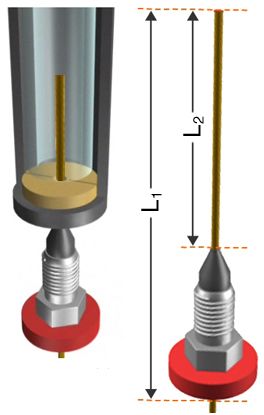
The distances between the ferrule tip and the column inlet are crucial and differ between manufacturers and determine the relative position of the column entrance within the inlet.
Ensure that guidelines for column insertion distances are followed closely.
Use the septum to keep the nut and ferrule at the correct position whilst inserting the column.
Note that you MUST consult your GC system manufacturer to find out the correct column length from the tip of the ferrule to the end of the column (L2).


If the column is incorrectly positioned, broad or chair shaped peaks or incorrect peak area ratios will occur to the increase in dead volume or incorrect sampling of analytes into the column.


Once the column length has been properly adjusted, insert the column into the inlet and finger tighten. If necessary, slide the septum to be snug to the bottom of the column nut to ensure the correct column insertion distance.
Ensure that the column is securely held in the injection port and that no leaks are present.
Care should be taken not to over tighten the column nut as this can break the ferrule (leaks and reduced sensitivity) and damage the end of the column (split or tailing peaks).
Tighten the column nut an additional half turn past the point at which the ferrule “just grips” the column in position.


7. To connect the GC Column to the Detector Port repeat the same procedure already described for the coupling of the GC column with the injection port.
Note that for sensitive detectors such as MS, you may want to condition the column prior to coupling the column into the detector port. Different column manufacturers have different recommendations for insertion distances into the detector port. These must be followed to avoid peak shape and quantitation issues.
Failure to install the column properly in the detector may lead to the introduction of large dead volumes in the sample path. This may manifest itself as peak tailing or, where the dead volumes are large, peak broadening.


8. Properly condition the column, see previous Tech Tip - GC Column Conditioning – Stop Wasting Time and Money!
I can’t stress enough that the quality of the column cut and insertion depth into the inlet and detector can have a huge impact on peak shape and quantitative reproducibility, so please make sure you pay good attention to these two factors and let’s keep up the 2396-year-old tradition!


Tony Taylor is the technical director of Crawford Scientific and ChromAcademy. He comes from a pharmaceutical background and has many years of research and development experience in small molecule analysis and bioanalysis using LC, GC, and hyphenated MS techniques. Taylor is actively involved in method development within the analytical services laboratory at Crawford Scientific and continues to conduct research in LC-MS and GC-MS methods for structural characterization. As the technical director of the ChromAcademy, Taylor has spent the past 12 years as a trainer and developing online education materials in analytical chemistry techniques.
 and is based in New Jersey, USA. He earned his two B.S. degrees at the University of Arizona and his Ph.D. in Chemistry from the University of Michigan under the direction of Prof. Robert T. Kennedy. Prior to joining BMS, he held a National Research Council position at the National Institute of Standards and Technology (NIST) and was a professor of chemistry at Temple University in Philadelphia, PA. To date he has authored more than 40 manuscripts and two book chapters. He has presented more than 40 oral or poster presentations and holds one patent in the field of separation science. Jonathan has proudly served on the executive board of the ACS Subdivision on Chromatography and Separations Chemistry (SCSC) for three terms.")


The LCGC Blog, Paying it Forward: Perspectives from a Fulbright–Palacky Distinguished Scholar
January 5th 2024In this LCGC Blog, Kevin Schug shares his plans for the future as a Fulbright–Palacky University Distinguished Scholar in the Czech Republic, and discusses why it is important to share analytical chemistry with communities around the world.