Split/Splitless Inlets in Gas Chromatography: What’s Up with All Those Different Glass Inlet Liners?

Over the winter break at the university where I work, I was ordering consumables for the upcoming semester. As I was browsing the web pages at a major vendor for glass inlet liners, I was again impressed by the many glass inlet liner options and geometries available for split and splitless inlets, still by far the most used today. In this installment, we review the processes that happen in the inlet when a sample is injected, and use this to make some sense of the many available inlet liner configurations. We generate some best practices and guidelines in selecting an inlet liner, but we see that there is no one single liner that fits all situations. Selecting the best inlet liner should be a step in all method development involving split or splitless injections.
Capillary gas chromatography (GC) has always suffered from some fundamental challenges regarding sample introduction into the chromatograph. First, the liquid sample must be transferred from a syringe or other sampling device to an open tubular column that most often has an inside diameter smaller than the syringe. Second, the injected sample must be vaporized and homogeneously mixed with the carrier gas stream. The sample/carrier gas mixture must be quantitatively and reproducibly trans- ferred into the open tube of the capillary column. Finally, the inlet must be large enough to accommodate the full vapor volume generated when the liquid sample is evaporated. As described in the classical book by Grob, Split and Splitless Injection in Capillary Gas Chromatography, the many processes involved with solving these challenges can be very complex, to the tune of this book being nearly 500 pages long (1).
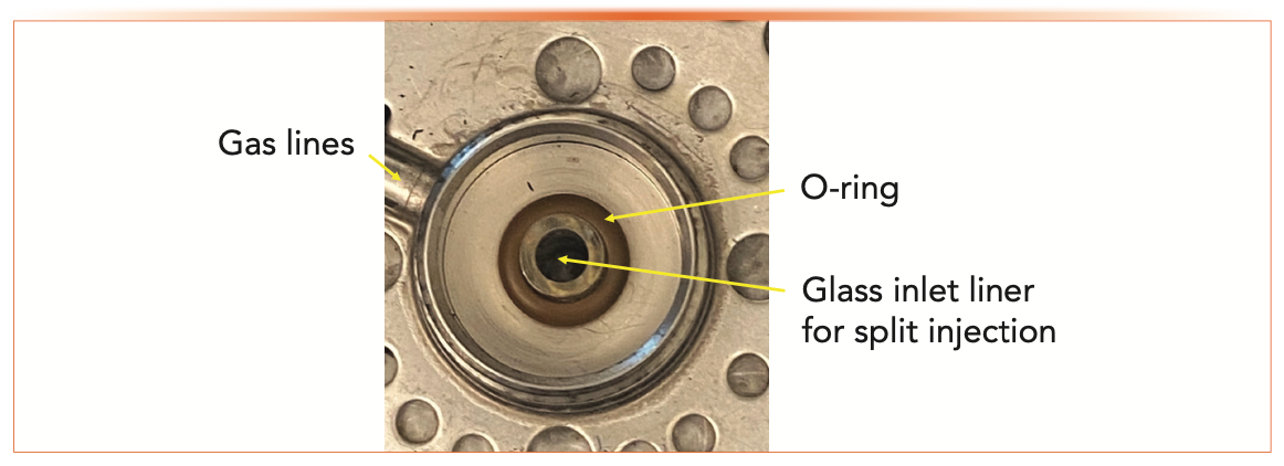
A final challenge involved in transferring a liquid sample into a capillary column is that the entire flow path must be inert. In his book, Grob describes that much research has been done over the years to ensure that the flow path is inert and does not react with or adsorb compounds from the samples. The flow path must also be easy to clean because it will eventually collect nonvolatile contaminants resulting from sample degradation. All of these challenges led to the development of glass inlet liners to provide an inert flow path that can accommodate the other challenges with vaporization of the sample, mixing with the carrier gas, and transferring that mixture to the column. Figure 1 shows a split/splitless inlet from above, with the top flanges, including the septum and septum nut, removed. Note that the inlet block and gas flow lines are all metal, which can be highly reactive with organic compounds when heated, and would be very difficult to clean. The inlet liner is glass, and usually fits loosely into the inlet body to allow for carrier gas to flow both through the inside of the liner and around the outside. An O-ring provides a gas-tight seal when the flanges and nuts are replaced. Details of the flow paths for split (and splitless) inlets and on general troubleshooting and maintenance of inlet systems are discussed in most texts including gas chromatography and on ChromAcademy, LCGC North America’s online learning platform (2). As a general maintenance and troubleshooting rule, the glass inlet liner and O-ring should be replaced together on a regular schedule, depending on the cleanliness of the samples being analyzed.


FIGURE 1: Close-up view of an inlet with the septum nut, septum, and top weldment removed showing the O-ring and glass inlet liner. The glass inlet liner has a wide inside diameter, indicating that it is for a split injection.
This maintenance rule highlights the need for a removable and replaceable liner for the flow path that also solves the several challenges. Even more challenging, a liner that works for one sample may not work for another. For the best performance, options must be tested and evaluated. In the remainder of this column, we examine principles of split and splitless injections that inform the choice of liner, beginning with some overriding concerns that govern all liners.
The Two Overriding Concerns: Inertness and Volume
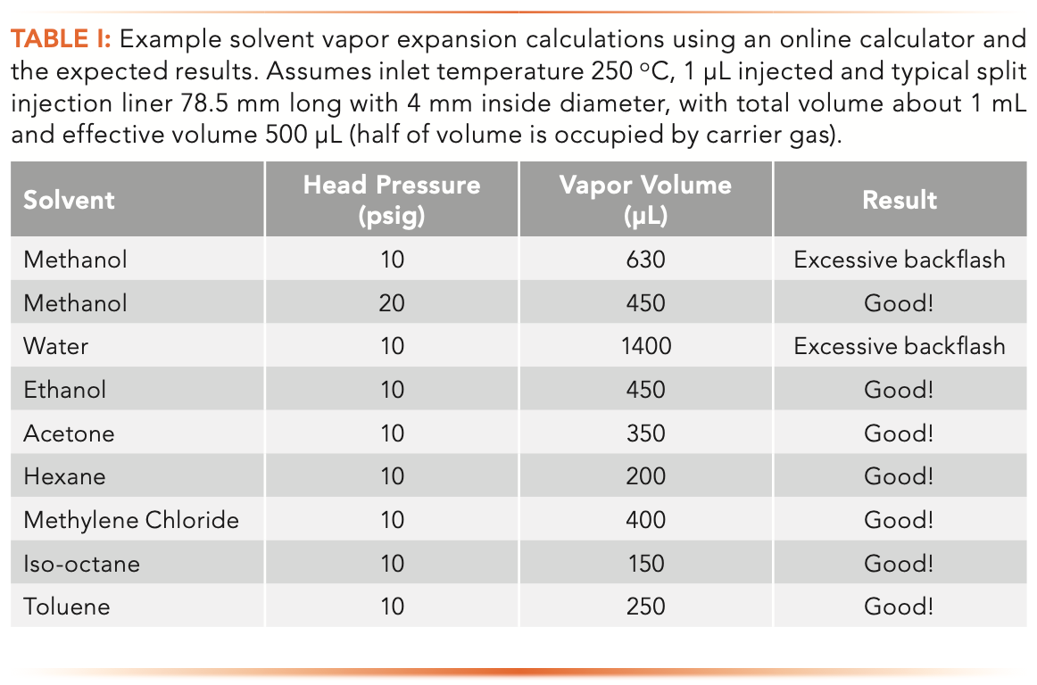
Regardless of the injection technique being used, the inlet liner must be inert to the samples, and must have large enough volume to accommodate the vapor generated when the sample is injected into the heated inlet and vaporized. Depending on the solvent, inlet temperature, and inlet pressure, typical sample solvents used in gas chromatography may generate anywhere from 200 μL to over 1 mL of vapor when evaporated in the inlet. If the volume inside the inlet liner is not large enough, vapor can backflow into the carrier gas lines. Because that vapor will also contain vaporized analytes, those analytes can condense in the gas lines and eventually become eluted as ghost peaks or baseline drift. Solvent vapor volume calculators for common solvents and inlet conditions are available online (3,4). These calculators can be used as guides for choosing the needed volume for the inlet liner. Generally, the chosen liner should have a higher internal volume then provided by the calculator. Table I shows vapor volumes generated using the two calculators for some common conditions. Excessive vapor volume occurs in relatively few situations, usually with polar solvents, high injection volumes, or low head pressure. Note that increased head pressure solved the problem with excessive evaporation of water.


The inlet liner must also be inert to any reactive compounds, both analytes and interferences. Nearly all inlet liners for split and splitless inlets are made from glass, which by itself is not deactivated and can have free silanol groups and other surface contaminants that can react with or adsorb analytes. One of the impressive options seen at the vendors’ websites is the choice of deactivation methods, which also should be matched to the expected reactivity of the analytes. Not surprisingly, deactivated inlet liners come at a higher individual price. Being an academic researcher, when devel- oping a method, I used to start with the most inexpensive option and move to the more expensive deactivated liners as needed.
Today, I simply purchase deactivated liners up front, so I do not have to find out the hard way, usually through poor peak shapes or poor quantitative reproducibility that I need to change to a more inert inlet liner. I also purchase deactivated liners from the vendors. I no longer attempt to deactivate them myself.
Next, we discuss glass liner choices for some specific situations, the most common split and splitless injections and some special cases, including solid-phase microextraction (SPME) and programmed temperature vaporization (PTV) systems.
Liners for Split Injections
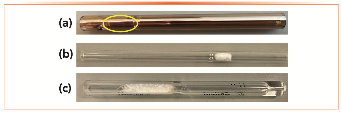
An ideal split injection requires that the sample be injected as quickly as possible, vaporized as quickly as possible, and mixed homogeneously with the carrier gas, with the mixture transferred rapidly to the column head. Rapid injection minimizes band broadening and is the primary cause of the sharp peaks characteristic of split injection combined with temperature programming. To assist in vaporization, split liners have large volume and often have obstructions, baffles or packing (glass wool or adsorbent) to facilitate vaporization. Figure 2 shows a typical cup-design glass inlet liner and two glass wool packed liners for split injections. I usually start with the cup design, developed by Jennings and often referred to as the “Jennings cup” (5). The cup and associated tubing provide a flow path that assists with vaporization by the large sur- face area and mixing by the twisted flow path. In Figure 2, the cup is highlighted by the yellow oval. Glass wool and baffles provide a less expensive alternative (especially glass wool for samples with a “dirty” matrix), but both can be challenging with reactive analytes; if active analytes are involved, I recommend the additional expense of deactivated liners. If you look closely at Figure 2c, you will see some contamination in the glass wool, providing evidence of the main challenge of using glass wool.

 Deactivated classical cup-design showing the high surface area and curved flow path. The cup is visible in the circled area. The glare is caused by the deactivation process; (b) simple straight tube with glass wool; (c) well-used straight tube with glass wool. Note the contamination near the taper in the middle of the liner.")
FIGURE 2: Inlet liners for split injections. (a) Deactivated classical cup-design showing the high surface area and curved flow path. The cup is visible in the circled area. The glare is caused by the deactivation process; (b) simple straight tube with glass wool; (c) well-used straight tube with glass wool. Note the contamination near the taper in the middle of the liner.
Liners For Splitless Injections
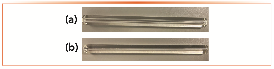
Splitless injection is a much slower process than split. A rapid injection with the syringe is followed by a slow evaporation and transfer of the vaporized sample to the column head. To reduce the band broadening caused by the slow sample transfer to the column, temperature programming is almost always used with splitless injections. The inlet liner for splitless injections must be a trade-off between adequate internal volume to accommodate solvent vapor and reasonable transfer time for the vapor phase solvent/solute/carrier gas mixture to the column. The classical liner is a straight glass tube with about 2 mm inside diameter, as seen in Figure 3a. A splitless liner usually has a smaller internal volume than for split. This is partially compensated by slower vaporization, but the liner volume should still be confirmed using a vapor volume calculator. The tube ends may be tapered or goosenecked to assist with column installation or syringe insertion. The liner may also be packed with glass wool or an adsorbent material to facilitate solvent and sample vaporization.

 2 mm inside diameter straight inlet liner for splitless injections; (b) 0.75 mm inside diameter straight inlet liner for SPME injections. Note the taper on the left end of the SPME liner which acts as a needle guide for the syringe.")
FIGURE 3: (a) 2 mm inside diameter straight inlet liner for splitless injections; (b) 0.75 mm inside diameter straight inlet liner for SPME injections. Note the taper on the left end of the SPME liner which acts as a needle guide for the syringe.
Special Liners: SPME and PTV
Most injections using solid-phase micro-extraction (SPME) are a special application of a split/splitless inlet in which no solvent is used. Because no solvent is used, there is no need for a large volume to accommodate solvent vapor. Since there is no need for a large volume, a small, 0.75 mm, inside diameter straight tube inlet liner is most commonly used. One advantage of SPME injections is that there is no solvent, so there is no need for the inlet liner to have a large internal volume; in fact, the smallest possible volume is best to reduce band broadening during the injection process. Figure 3b shows a typical glass liner for SPME. Note the vary narrow inside diameter, which is possible since there is no solvent vapor and the taper at one end, which provides a guide for the needle to fit more easily into the small diameter. In the early days of SPME, my group wrote on the details of optimizing SPME injections using the split/splitless inlet (6). The narrow diameter liner becomes more critical as the analytes become more volatile. For semi-volatile analytes, a traditional straight splitless liner will often work.
You may have a programmed temperature vaporization (PTV) or multi-mode inlet that is capable of several injection techniques in a single platform. The basics of these inlets were discussed in a previous “GC Connections” installment (7). If temperature programmed inlets are used, the inlet and the inlet liner must have a low thermal mass for rapid heating and cooling, so inlet liners are typically large internal volume with thin glass walls. If large volume injections are performed, the inlet liner usually contains an adsorbent to accommodate the large volume of injected liquid solvent.
Choosing a Liner
Basic characteristics of inlet liners for specific injections methods are summarized in Table II along with my recommendations for a starting point in method development.

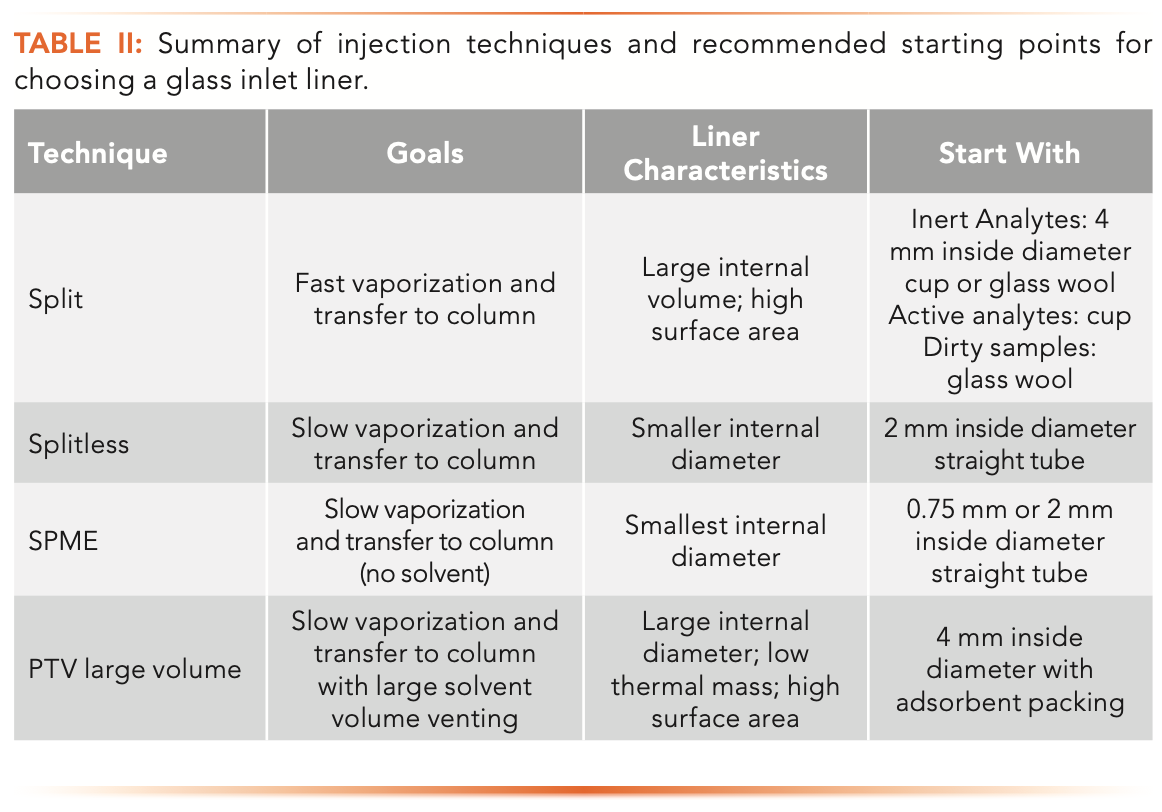

When I am choosing inlet liners, I start simple. For split injections, I start with a classical cup design, which, although a little more expensive than some of the other options, provides a large space for vapor expansion and a high heated surface area to aid in sample vaporization. Also, the cup prevents an accidental “lucky shot” in which the liquid stream from the syringe shoots straight into the column. For splitless, I prefer to start with a 2 mm inside diameter straight tube, with no glass wool or other obstructions. I then consider options for a modified flow path, such as glass wool, should my evaluation of the data dictate, usually by seeing unsatisfactory quantitative reproducibility for repeated injections of standards. The challenge with choosing a glass inlet liner is that there is no solution that fits all analyses and situations. Once a starting point is chosen, if the results are not satisfactory, alternatives must be selected and tried by experimentation. Finally, when choosing a glass liner for a specific application, the classic first steps in method development especially apply: check the applications literature, and contact the vendor for advice as well as ask someone who knows.
Conclusions
The glass inlet liner is one of the most important, yet least understood and most often ignored, components of a gas chromatographic experiment. It is the critical link between sample preparation and separation by the column. The best sample preparation and the best column can be ruined by a poor choice of glass liner. Unfortunately, there is no “killer app” for choosing an appropriate glass inlet liner. Users are best served by making an intelligent first choice, usually simple, and of course appropriate to the injection tech- nique (split or splitless) being used, thinking about the expected chemistry of their samples and standards and making changes such as from cup to baffles to inserting glass wool as analytical and chromatographic performance dictate. Not all glass inlet liners are alike, and not all will solve every problem. For best performance, they must be studied by experiment.
References
(1) K. Grob, Split and Splitless Injection for Quantitative Gas Chromatography: Concepts, Processes, Practical Guidelines, Sources of Error (John Wiley and Sons, Hoboken, NJ, 4th Ed., 2001).
(2) “GC Sample Introduction” ChromAcademy, https://www.chromacademy.com/channels/gc-training-courses/instrumentation/gc-sample-introduction/ (accessed February 2022).
(3) Agilent Solvent Vapor Calculator, https://www.agilent.com/en/support/gas-chromatography/gccalculators (accessed February 2022).
(4) Restek Solvent Expansion Calculator, https://www.restek.com/en/tools-and-calculators/ tools/solvent-expansion-calculator/ (accessed February 2022).
(5) W.G. Jennings, J. Chromatogr. Sci. 13, 185 (1975).
(6) P.D. Okeyo and N.H. Snow, LCGC North Am. 15(12), 1130–1136 (1997).
(7) N.H. Snow, LCGC North Am. 37(7), 392–395 (2020).
ABOUT THE AUTHOR


Nicholas H. Snow is the Founding Endowed Professor in the Department of Chemistry and Biochemistry at Seton Hall University, and an Adjunct Professor of Medical Science. During his 30 years as a chromatographer, he has published more than 70 refereed articles and book chapters and has given more than 200 presentations and short courses. He is interested in the fundamentals and applications of separation science, especially gas chromatography, sampling, and sample preparation for chemical analysis. His research group is very active, with ongoing projects using GC, GC–MS, two-dimensional GC, and extraction methods including headspace, liquid–liquid extraction, and solid-phase microextraction. Direct correspondence to: LCGCedit@mmhgroup.com


, also known as an immunoglobulin (Ig). 3d vector.")


TD-GC–MS and IDMS Sample Prep for CRM to Quantify Decabromodiphenyl Ether in Polystyrene Matrix
April 26th 2024At issue in this study was the certified value of decabromodiphenyl ether (BDE 209) in a polystyrene matrix CRM relative to its regulated value in the EU Restriction of Hazardous Substances Directive.

 and Dr. Valérie Agasse (right) of the University of Rouen. Photo Credit © Pascal Cardinael and Valérie Agasse.")
Inside the Laboratory: The Chromatography Laboratory at the University of Rouen
April 18th 2024In this edition of “Inside the Laboratory,” Pascal Cardinael and Valérie Agasse of the University of Rouen in Mont‑Saint-Aignan, France, discuss their laboratory’s work with miniaturizing gas chromatography (GC) columns and systems to improve on-site air analysis of volatile organic compounds (VOCs).