Making Connections
LCGC North America
This month's "LC Troubleshooting" takes a look at the important components that are used to connect various parts of the LC system and how to use them wisely.
Sometimes it is easy to ignore the fittings and tubing that are used to connect various parts of the liquid chromatography (LC) system. After all, it's the pump, injector, column, and detector that do all the work — right? Well, yes and no. It is possible to compromise an otherwise excellent separation by the improper use of fittings, but with reasonable care, you should not have problems with most applications. This month's installment of "LC Troubleshooting" takes a look at the important components that are used to connect various parts of the LC system and how to use them wisely.


John W. Dolan
Compression Fittings
The compression fitting forms the basis of the system connecting LC system modules. These fittings are quite simple in design, as shown in Figure 1, which depicts a tube fitting and a union. The tube end comprises a nut, ferrule, and the tube itself. The tapered ferrule slips onto the tubing and, when tightened against the matching taper in the fitting body, forms a leak-free seal. When stainless steel components are used, the ferrule is crimped, or "swaged" onto the tubing so that it no longer slips freely on the tubing. The location of the ferrule on the tubing is dictated by the depth of the fitting port in the mating fitting body.
The fitting body can be a union, as shown in Figure 1, that connects two pieces of tubing, or it can be a check valve, column end, or any other system component that requires connection to a piece of tubing. When assembled properly, as in Figure 1c, a union provides no appreciable disruption of the flow path, so it should not cause any degradation of the chromatogram. Such connections are called "zero-volume" or "zero-dead-volume" connections. This is what we strive for when making connections between the various parts of our LC systems.

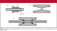
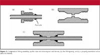
Figure 1
Connection Problems
Two types of problems are of special concern when a tube connection is made. Both of these relate to the setback of the ferrule ("X" in Figure 2) from the end of the tubing. This distance is dictated by the depth of the fitting port in which the tube end is originally assembled. If the original port is deep, the setback will be large, and when reassembled in a shallower fitting port, the tube end will bottom out in the fitting port before the ferrule contacts the mating seat. This can result in a leaky connection. If a connection leaks, most of us tend to tighten the fitting nut a little more to see if we can stop the leak. Although the ferrule is swaged onto the tubing, it is not welded in place, so tightening the nut usually will push the ferrule down the tube until it seats properly. In such cases, the problem is solved and the fitting should function properly. However, if the original fitting was overtightened, the ferrule can be swaged so tightly that it does not move, and the leak will persist.

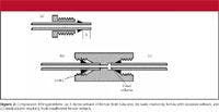
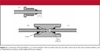
Figure 2
The other type of common problem occurs if the tube end was originally assembled in a fitting with a shallow port, resulting in a small setback for the ferrule. (This also can occur as described previously if a large setback ferrule is pushed toward the end of the tube.) When this tube end is assembled in a deeper fitting port, the ferrule appears to seat properly, so no leak will be observed, but a small gap will be left at the end of the tube. This gap can cause additional mixing, disturb the flow path, and add dead volume to the system. With LC separations on modern columns, peaks passing through such connections can become broadened or distorted. This type of problem is of more concern than a leaky fitting because there often is no visual problem when the fitting is first assembled.
There is a potential for problems due to differences in ferrule setback whenever a tube end is moved from one connecting point to another. Different manufacturers may use different port depths in their unions, column endfittings, check valves, or other system components.
Extracolumn Band Broadening
The influence of poorly assembled tube fittings shows up as peaks that are broader than expected. This is referred to as extracolumn band broadening. The peak width that is observed in a chromatogram Vp can be expressed as the sum of the variances of its contributing parts:


where the subscripts represent the volume contribution to the total peak by the column, fittings, tubing, injector, and detector. All of these, except the column, are fixed for a given instrument setup and together are referred to as extracolumn contributions (Vec). The contribution to the peak width by the column, on the other hand, varies for a given separation. Under isocratic conditions, the longer the peak is retained, the broader it is, so its volume (time × flow rate) increases. In addition to varying width with retention time, narrower peaks are generated by smaller-particle (3 μm versus 5 μm), shorter (50 mm versus 150 mm), and narrower internal diameter (2.1 mm versus 4.6 mm) columns. It can be seen that a fixed value of Vec will have a larger relative contribution to a narrow peak (small Vc) than a larger peak (larger Vc). Most of us use 150 mm × 4.6 mm columns packed with 5-μm particles, and with reasonable care in the use of fittings and tubing we will rarely, if ever, notice a problem created by a poorly assembled fitting. However, as changes in the LC technology push some of us to use columns that generate much smaller volume peaks (for example, 50 mm × 1.0 mm columns packed with <2-μm particles), problems due to the extracolumn contributions of tubing and fittings will begin to take on new importance.
Enter the Fingertight Fitting
For most applications, the problems described previously, originating from poorly assembled fittings, should be history. This is because of the introduction of the Fingertight fitting by Paul Upchurch (Upchurch Scientific, Oak Harbor, Washington) in the 1980s. This is one of those "why didn't I invent this" ideas that wasn't as impressive in its innovation in design as in its practical impact on the day-to-day life of practicing chromatographers. Originally offered as a single-piece Kel-F fitting that combined the nut and ferrule, today's fingertightened fittings (now offered by many suppliers) comprise a nut and ferrule, as in Figure 1, but made of PEEK (poly-ether-ether-ketone) instead of stainless steel. The beauty of this design is that it can be assembled in one fitting body and then moved to another. When tightened, the ferrule grips the tubing to form a leak-free junction (for example, up to 4000 psi or more), but when loosened, the ferrule slips freely to allow adjustment for assembly in a different fitting body. The ability to tighten the fittings with finger pressure rather than a wrench adds convenience and eliminates broken parts due to overtightening.
I recommend strongly the use of fingertightened fittings in nearly every LC application. If I want to make a connection once and never change it, such as inside an autosampler, or from a pump outlet to a mixer, I prefer stainless steel, because it will not slip, even if the system is overpressured. For applications at very high pressures (>>6000 psi; >>400 bar), stainless steel probably will be required, because most plastic fittings will leak. However, most of the routine LC applications will work just as well with fingertightened as with stainless steel fittings.
If a fingertightened fitting leaks, don't just tighten it up and hope for the best. Shut off the pump, loosen the fitting, reseat the tube end firmly in the fitting port, and then retighten the nut before turning the flow back on. The reason for these extra steps is that with pressure in the system, tightening the nut can reduce the friction between the ferrule and the tube end so that the tube end can be pushed out of the connection. It may not be pushed completely out, but may move enough to leave a gap in the fitting that can cause extracolumn band broadening.
What About Tubing?
We have seen the importance of properly assembling tube fittings; let's look next at the choices in tubing. Table I lists some of internal diameters of tubing available for LC use. An outside diameter of 1/16 in. is most common in the US — elsewhere, metric sizes are more popular. The internal volume for various internal diameters is estimated in Table I also. The larger sizes of tubing (≥0.020-in. i.d.) are used mostly for injection loops because it is possible to get a significant volume in a short piece of tubing. Just the opposite is required for tubing used to transport the sampler — the volume should be minimized to minimize the contribution of Vt to band broadening in equation 1. Historically, 0.010-in. i.d. tubing was used, but with 5-μm particle columns, 0.007-in. i.d. tubing is favored. This is a good compromise between small internal volume and robustness. The smaller, 0.005-in. i.d. tubing gives still smaller internal volumes, but extra care should be taken to avoid blockage. If you use this tubing, I strongly recommend the use of a 0.5-μm porosity in-line filter just downstream from the autosampler to help minimize blockage problems.


Table I: Tubing size conversions
As with fittings problems, problems due to excess tubing volume seldom will be noticed in most routine applications of 150 mm × 4.6 mm, 5-μm particle columns. Extra care should be taken when using columns that generate smaller peak volumes.
Tubing Composition
Stainless steel tubing has served well from the beginnings of LC in the 1960s until the present. Just as many workers have moved to fingertightened fittings from stainless steel ones, PEEK tubing has supplanted stainless steel in many applications. PEEK tubing is inexpensive and easy to use. It can be cut with a sharp blade and is sufficiently flexible to route easily from one component to another. Most manufacturers color their PEEK tubing, so one can easily determine the internal diameter from the color. PEEK tubing pressure limits are lower than stainless steel, so it generally is used for applications at ≤4000 psi (≤300 bar).
One caution that should be taken with PEEK tubing is its solvent compatibility. PEEK is not suitable for use with tetrahydrofuran or the chlorinated solvents. (There are a few other less common solvents that cannot be used — check the manufacturer's literature for a listing.) These solvents tend to make PEEK brittle, and with extended use, the tubing can snap when it is bumped. In the early days of PEEK tubing, our laboratory did extensive testing to see if we could find any problems with UV interferences leaching from the tubing with acetonitrile, methanol, or tetrahydrofuran. We did not see any problems with UV detection and PEEK, and I have not heard of any complaints in this area, so the main risk of using tetrahydrofuran is a broken tube. However, tetrahydrofuran does leach something from the tubing that can cause a large increase in background interferences with mass spectrometric (MS) detection, so I strongly recommend obeying the solvent compatibility recommendations for PEEK when using LC–MS. Conventional acetonitrile and methanol mobile phases for LC–MS work well with PEEK.
How Much?
Charts are available that describe how much tubing is allowed for a certain amount of loss of resolution (for example, see reference 1), but I find these of limited use for practical applications. My advice is to keep the tubing that contacts the sample to a minimum length. If you are using a 150 mm × 4.6 mm column with 3-or 5-μm particles and UV detection, and can keep the total amount of tubing between the injector and detector to ≤50 cm, you will find 0.007-in. i.d. tubing satisfactory. If you are using a column that generates smaller peak volumes or you need more tubing, 0.005-in. i.d. tubing is a better choice. For example, with LC–MS applications, because of instrument layout, it is difficult to make all the connections with less than about 1 m of tubing, so 0.005-in. i.d. tubing is a must. If you want to get the maximum performance out of your column for any application, use 0.005-in. i.d. tubing and arrange the LC components so the column inlet is close to the autosampler and the outlet is close to the detector. Once again, though, most of our applications don't demand maximum plate numbers from the column, and as long as we're not overly sloppy with extra-long pieces of large diameter tubing, most of us will never encounter problems due to excess tubing.
The Bottom Line
Tubing and fittings used for LC applications often are overlooked as a problem area. This is justified for most conventional applications. However, as the technology pushes us to conditions that generate narrower peaks, we should take a little extra care to avoid extracolumn band broadening due to improper use of tubing and fittings. Take care to ensure that the tube ends are seated firmly in the fittings before tightening the nut. Use PEEK fittings and tubing for convenience. Stick with 0.007-and 0.005-in. i.d. tubing, and keep the lengths at a convenient minimum. Follow these simple guidelines and you won't have to worry about tubing and fitting problems.
"LC Troubleshooting" Editor John W. Dolan is Vice-President of LC Resources, Walnut Creek, California; and a member of LCGC's editorial advisory board. Direct correspondence about this column to "LC Troubleshooting," LCGC, Woodbridge Corporate Plaza, 485 Route 1 South, Building F, First Floor, Iselin, NJ 08830, e-mail John.Dolan@LCResources.comFor an ongoing discussion of LC troubleshooting with John Dolan and other chromatographers, visit the Chromatography Forum discussion group at http://www.chromforum.com.
References
(1) J.W. Dolan and L.R. Snyder, Troubleshooting LC Systems (Humana Press, Totowa, New Jersey, 1989), Table 8.3.


")


 - stock.adobe.com")
Investigating PFAS in Plastic Food Storage Bags Using LC–MS/MS
May 8th 2024Yelena Sapozhnikova from the United States Department of Agriculture spoke to The Column about her innovative research investigating PFAS in plastic food storage bags using targeted and non-targeted liquid chromatography–tandem mass spectrometry.


Vitamin D Determination Tested Using Liquid Chromatography–Tandem Mass Spectrometry
May 2nd 2024Scientists from Hangzhou Medical College recently recorded the effectiveness of novel quality control strategies for the determination of vitamin D using liquid chromatography–tandem mass spectrometry (LC–MS/MS).