
|Articles|December 5, 2017
- The Column-12-05-2017
- Volume 13
- Issue 17
Tips & Tricks GPC/SEC: How to Treat Your RI Detector
Author(s)Daniela Held
The refractive index (RI) detector is the most common detector in gel permeation chromatography/size-exclusion chromatography (GPC/SEC). The advantage of this universal detector is that it detects everything; the disadvantage is that it detects everything. This instalment of “Tips & Tricks” offers some advice when working with RI detectors.
Advertisement
Daniela Held, PSS Polymer Standards Service GmbH, Mainz, Germany
The refractive index (RI) detector is the most common detector in gel permeation chromatography/size-exclusion chromatography (GPC/SEC). The advantage of this universal detector is that it detects everything; the disadvantage is that it detects everything. This instalment of “Tips & Tricks” offers some advice when working with RI detectors.
Gel permeation chromatography/size-exclusion chromatography (GPC/SEC) is the method of choice for determining the molar mass distribution of synthetic and natural polymers. Every GPC/SEC system requires at least one concentration detector in the setup to allow for the detection of the fractions eluting from the column. Typical detectors used are refractive index detectors (RIs), ultraviolet (UV), diode array detectors (DAD), photodiode array detectors (PDA), or evaporative light scattering detectors (ELSDs). Each of these detectors has its advantages and disadvantages. This instalment of Tips & Tricks compares the RI to other concentration detectors and provides practical tips when using it.
How Does an RI Detector Work?
In general, RI detectors respond to a change of the refractive index, n. Most detectors are differential refractometers. They measure the deflection of a light beam from the difference in the refractive index between pure solvent and solvent with sample. This difference is referred to as ân and is expressed in refractive index units (RIU).
Figure 1 shows how that can be achieved by using a detector flow cell divided diagonally into two parts. The cell therefore comprises a sample-containing side filled with the column effluent and a non-sample-containing reference side. If both sides contain the same mobile phase the detector is in optical balance. When sample elutes from the column, the refractive index in the sample-containing side will change and the light beam will be deflected.
RI detectors are therefore very universal detectors. Compared to UV detectors they do not require chromophores in samples. They can detect all types of samples including polysaccharides, starches, and polyesters. Compared to ELSDs, which do not require chromophores either, they are much more linear in response and evaporating the solvent is not required. Therefore, RIs can be used with all types of solvents with or without salt. In addition, RIs are able to detect oligomers and contaminants as residual monomer, which could be evaporated when using ELSDs.
Disadvantages of RI Detectors
At a fixed wavelength of incident light the changes in refractive index are generally linear in relation to the changes in medium density. However, the density of a medium is also affected by composition, temperature, and pressure. Therefore, the refractive index will change with solvent composition, traces of contamination, degassing level, temperature fluctuations, and more. One consequence of this is that an RI detector can only be applied in isocratic mode-solvent gradients are not possible. Another consequence is that the RI will respond to any change in the experimental conditions with a change in its signal and a variation of its baseline. It sometimes appears as if RIs are unstable or generate unstable baselines, when in fact, RIs are simply displaying the instabilities of the environment and the rest of the system.
It should be also kept in mind that RIs are in general not as sensitive as UV detectors or ELSDs are. They need relatively high concentrations compared to other detectors.
How to Handle an RI Detector
The cell design and the principle of the RI detector have some consequences for practical work. In a multidetector setup, which is very typical in GPC/SEC, the RI often has to be the last detector in the daisy-chain (1,2). The main reasons for this are that the cell can withstand only low backpressures, the cell and the tubing in the detector often have large dimensions leading to band broadening, and the signal itself is pressure sensitive.
The vast majority of an RI needs flushing or purging of the reference cell. To achieve a stable baseline, the solvent in the reference cell and the mobile phase must be the same quality. The reference cell must be flushed or purged regularly, and at the very least when the mobile phase in the reservoir is changed.
The best time to purge or flush the RI is directly prior to the analysis as the last action after the system and the columns have been thoroughly flushed and had time to stabilize. If purge or flush is performed while the system (or the columns) are still equilibrating, the solvent in the reference cell will be of a different quality to the sample cell. No optical balance can be achieved before the run and low signal quality may be a problem during the run.
Troubleshooting for RI Detectors
Figure 2 shows a common RI trace obtained for a mixture of four different polymethyl methacrylate (PMMA) reference materials with different molar masses. The system peaks at the end of the chromatogram are very typical. These peaks can be only negative (as in the example), but a combination of negative and positive peaks is also common. The system peaks indicate the end of size exclusion mode.
It is good practice in GPC/SEC to prepare the samples in solvent taken from the mobile phase reservoir to reduce the system peaks to a minimum. The larger the difference between the solvent used for sample preparation and the mobile phase, the larger the system peaks will be. System peaks are identified by measuring a blank sample within the sequence and overlaying this with the samples. It is important that the blank is treated the same way as the samples themselves including all filtration steps.
Problems that can occur with RI detectors are mainly the same as for other detectors in GPC/SEC. Typical are baseline drift (the steady movement of the baseline, either up or down the scale), baseline wander (variation of the detector with frequencies between 6 and 60 cycles/h), and detector noise (variation of the detector signal with frequencies above 1 cycle/s) (3). The inset in Figure 2 shows the values for baseline drift, signal noise, signal wander, and signal-to-noise ratio (S/N), if applicable compared to the requirements of ISO13885-1.
S/N Ratio: When discussing the S/N, it is important to understand the RI detector response to a sample. The RI signal intensity depends on the concentration and the refractive index increment, dn/dc.
For a sufficient S/N two parts need to be considered:
1) The larger the concentration, the larger the signal area. In Figure 2 all PMMAs have the same dn/dc, so the same concentration should result in the same area. This is true for this example because the highest molar mass (eluting around 6 mL) has only half of the concentration compared to the three other lower molar mass samples resulting in only half of the peak area (4).
2) The larger the dn/dc, the larger the signal area. For example, if a polystyrene (PS) mixture with the same molar masses and concentrations is measured, the PS signals will be higher than the PMMA signals because of the higher dn/dc of PS compared to PMMA (conditions: THF, 35 °C). If the dn/dc is 0 (isorefractive samples), such as for polydimethylsiloxane (PDMS) in THF, no signals or only small signals resulting from end groups will be obtained when using an RI. Here another solvent, such as toluene, needs to be used to obtain representative signals with good S/N. As the dn/dc is negative for PDMS in toluene, negative signals will be obtained. It is possible to either inverse the signal at the RI directly or in the corresponding software to evaluate them properly.
Baseline Drift: As mentioned earlier, RIs show instabilities of the environment and the rest of the system. There are three major sources for baseline drift: low mobile phase quality, temperature differences between the columns and the RI cell, or a not yet equilibrated system. Using freshly prepared, high-quality solvent, thoroughly thermostatted columns and RI detector cells, and providing enough equilibration time for the system should take care of this issue.
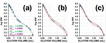
Baseline Wander: Worse than drift-which can be easily corrected (especially when using the recommended two-step evaluation procedure [5])-is detector wander. Figure 3 shows a nice example of detector wander. The reason for the signal fluctuations was a degasser not suited for this GPC/SEC solvent. After removing the degasser completely from the setup, the signal quality was stable again.
Similar traces are also observed when the degasser is not working properly (because of low solvent quality or malfunctioning of the vacuum pump) or if the column oven temperature is not stable enough (heating cycles). In both cases working without a degasser or column oven yields better results than working with low quality components. The air conditioning installed in the laboratory could also evoke detector wander.
Other Problems: A very interesting troubleshooting example is shown in Figure 4. Here the signal of the internal standards (like that of the other samples in the following injections) starts negative and then becomes directly positive with a steep increase in between. The reason for this behaviour was located in a defective purge valve. The reference part of the cell was therefore not completely shut during analysis and the sample was flowing through both cell parts, resulting in one positive and one negative signal. The same behaviour would be observed if a sample was run in activated RI purge or flush mode. A replacement of the purge valve took care of this problem.
The signal split does not have to be as pronounced as in the example. Sometimes the process starts with a small negative dip before the signal starts. However, once the valve is fully damaged the signal will be as shown in the example.
Summary
- RI detectors are universal detectors with a linear response suitable for many different types of macromolecules. They do not require chromophores because they respond to a change in refractive index.
- RIs are typically used as concentration detectors in GPC/SEC. When applied in GPC/SEC light scattering setups they are often used to estimate the refractive index increment, dn/dc.
- The disadvantages of RIs are that they not very sensitive, they are affected by environmental conditions, and they have a reference cell.
- RI detectors require high solvent quality for stable baselines.
- Purging or flushing of the RI reference cell should be done as the last action prior to the analysis and only for fully equilibrated systems.
References
- D. Held and P. Kilz, The Column8(18), 9–12 (2012).
- D. Held and W. Radke, The Column13(11), 9–14 (2017).
- D. Held, The Column8(6), 13–18 (2012).
- D. Held, The Column10(10), 12–15 (2014).
- D. Held, The Column9(2), 2–5 (2013).
Daniela Held studied polymer chemistry in Mainz, Germany, and works in the PSS software and instrument department. She is also responsible for education and customer training.
Articles in this issue
over 8 years ago
Instrumental Innovations 2017over 8 years ago
Peak Introduces Free to Use GC Gas Calculatorover 8 years ago
Kevin Schug Earns ACS Education Excellence Awardover 8 years ago
Dwight Stoll Receives EAS Young Investigator Awardover 8 years ago
Sciex Announce China Expansionover 8 years ago
Get More Separation Power With Multidimensional Chromatographyover 8 years ago
The Durian Tang: Investigating the World’s Smelliest Fruitover 8 years ago
Vol 13 No 17 The Column December 05, 2017 Europe and Asia PDFAdvertisement
Related Content
Advertisement


Advertisement
Advertisement
Trending on LCGC International
1
AI/ML in Practice: Machine-learning Prediction of Chromatographic Retention Times for Small Molecules in Pharmaceutical Applications
2
Emerging Contaminants and the Shifting PFAS Landscape
3
Fast GC-MS/MS Detects PFAS in Food Packaging
4
Chromatography's Role in Spotting False Leachables
5