|Articles|May 1, 2008
- LCGC North America-05-01-2008
- Volume 26
- Issue 5
Dynamic Extraction: A High-Speed, High-Capacity Purification Process That is Rapidly Scalable
The authors discuss a preparative process using the principles of countercurrent chromatography. This process is faster, capable of loadings from milligrams to hundreds of grams, and uses robust equipment.
Advertisement
As every working scientist knows, it is becoming increasingly important for industry to improve efficiency, reduce costs, and shorten the time taken to develop purification processes. Dynamic extraction (DE) is the name given to the modern, high-speed, high-capacity, preparative-scale development of countercurrent chromatography (CCC) and is a technique that is tackling some of these issues. Whereas CCC is known as a slow technique (separations measuring in hours or days) with poor capacity (injection amounts measured in tens of milligrams), poor reliability (instruments that frequently broke down), and difficult scale-up (no understanding of the factors required to scale-up or instruments on which to do so), with dynamic extraction, the separations are provided in minutes, the injection loadings are in the grams to hundreds-of-grams scale, the equipment is considerably more robust, and the scale-up from analytical to pilot level has been shown to be quick and easy (1,2). These developments have resulted from recent engineering improvements and advances in the understanding of the process, giving rise to a range of dynamic extraction instruments capable of purifying pilot-scale amounts of crude material, with advantages over both solid-phase chromatography and traditional liquid–liquid extraction. It should be noted however, particularly with the references quoted, that the terms CCC and DE still are interchanged freely in the literature, and the defining line between the two is not established definitively.
Description of Dynamic Extraction
In DE centrifuges, tubing is wound in a coil onto a drum (called a bobbin) that is rotated centrifugally in planetary motion; that is, it revolves around the central axis of the sun gear while simultaneously rotating about its own axis at the same angular velocity (Figure 1). A two-phase solvent system is placed inside this coil. A simple example of such a system would be heptane–water but a more likely system for a purification might consist of heptane, ethyl acetate, methanol, and water. This creates a two-phase system with an upper, organic layer consisting mainly of heptane–ethyl acetate and a lower, aqueous layer consisting mainly of methanol–water.
Figure 1
When the coil is rotated with the two-phase solvent system inside, the planetary motion creates a mixing effect akin to the "swish-swosh" motion that occurs when a tube of two liquids is tilted from side to side (Figure 2). The net result of this motion is the formation of waves and a wave mixing effect (Figure 3).
Figure 2
As the coil travels through its planetary motion cycle, zones of mixing and settling travel along the phases coincident with the low and high accelerations caused by the epicyclic motion of the coil. The mixing zones are coincident with low accelerations and take the form of the waves mentioned previously. The settling zones are coincident with high accelerations and take the form of a smooth interfacial area. The net result is illustrated in Figure 4, in which the mixing zone is seen on the left of the image and the settling zone on the right.
Figure 3
When a sample is introduced into the centrifuge, it will experience a series of mixing and settling steps according to the low or high acceleration vectors. It will be noticed that there is one mixing and one settling zone per coil loop. In the case of Figure 4, four coil loops are illustrated and therefore, four mixing zones and four settling zones. The coil is wound in an axial direction, producing a helical coil. In practice, a typical coil will be multilayer wound, can have 30 loops, and will spin at 1200 rpm. It will therefore undergo 2.16 million partitioning steps per hour (30 × 1200 × 60). This provides for high-resolution separations based upon each component's differential partitioning behavior, as characterized by the distribution ratio (KD = concentration of solute in stationary phase/concentration of solute in mobile phase).
Figure 4
The synchronous planetary motion of the DE bobbin has a special feature significant in the design of instruments: there is no twisting of the flow tubes linking the coil to the pump and detector. This is because the rotation about its own axis unwinds the twist produced by its motion around the sun gear.
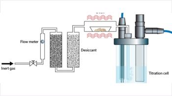
The arrangement for a typical DE setup is the same as that for the old CCC designs (Figure 5). In effect, the DE coil is equivalent to a preparative high performance liquid chromatography (HPLC) column. All the ancillary equipment is the same — pumps, injection valves, detector, fraction collector, and chromatography software. Two pumps allow the easy switching of stationary to mobile phase (remember, both phases are liquid), while a nitrogen cylinder allows the final extraction of the liquid stationary phase from the coil if that is desired. An upstream valve selects which phase is used. The injection valve can be a standard Rheodyne type. However, whereas DE is capable of handling crude, viscous samples with particulates, often the injection valve is not, so direct injection from a syringe might be necessary. The downstream valve diverts the liquid stationary phase away from the detector until equilibrium has been reached, avoiding potential problems with droplets of one phase trapped in the detector cell. The diagram shows a UV detector, which is nondestructive. However, DE is used commonly with a bleed to an evaporative light scattering detector and has even been used with mass spectrometry detection (3).
Figure 5
To perform a preparative DE run, the coil initially is filled with the solvent phase intended to be stationary and the spin is started. The mobile phase is then pumped into the coil. A small initial displacement of stationary phase occurs before a hydrodynamic equilibrium is set up, with the spinning planetary motion retaining up to 95% of the liquid stationary phase in the coil (primarily depending upon the solvent system, spin speed, and flow rate), and the mobile phase passing through, emerging at the far end without displacing any more stationary phase.
Dynamic extraction can be used in normal- or reversed-phase mode, depending upon which solvent phase is selected to be stationary. Furthermore, material that is eluted very slowly can be recovered by pushing out the stationary phase without any compound losses while maintaining resolution (4).
Figure 6
At the Brunel Institute for Bioengineering (London, UK), we have a range of dynamic extraction centrifuges running from analytical to pilot scale, the latter capable of processing up to 6 kg/day (Table I). Known in the institute as Mini, Midi, and Maxi, the Mini-DE centrifuge is the size of a portable TV, the Midi fits into a normal chemistry fume cupboard, and the Maxi is a pilot machine about 2 m3 in size (Figure 6). A "super-Maxi," with a coil volume four times the existing machine, currently is being constructed.
Table I: The range of dynamic extraction centrifuges with their specifications.
Advantages of Dynamic Extraction
The key advantages of the technology are:
- High loading capacity with short processing times. Even the smallest centrifuge, with a 17-mL coil and running at a 1 mL/min flow rate, is capable of accepting an injection of up to 50 mg of crude material.
- No losses arising from irreversible adsorption onto solid matrices. 100% recovery of the sample components.
- Far lower solvent usage compared with solid phase chromatography systems operating at the same scale. Furthermore, a simple analysis of solvent composition allows the recycling of the solvents, reducing the usage still further (5).
- One-step purification of compounds from a crude extract is possible, without the need for prior sample clean-up procedures. Particulates such as cell debris are tolerated, so filtering a crude sample is not necessary.
- A wide range of polarities can be processed due to the range of solvents that can be used. The literature reports examples with a logP range of at least –4.65 (colistin peptide antibiotic) (6) to logP +17.6 (lycopene) (7).
- Separation of proteins and other biomolecules is being developed using aqueous–aqueous two-phase systems such as polymer–salt systems (8).
- There is no change to the column over time (no aging effects) as a fresh column is used each run. This makes it easier to satisfy current regulatory requirements consistently under a GLP or GMP environment.
- The coils are tough and the machinery robust. A set of coils would be expected to last the lifetime of the centrifuge and so maintenance and running costs are low.
Solvent System Selection Process
With its high loading, total recovery of components, and ability to perform a one-step purification from crude material, dynamic extraction is fundamentally a preparative technique. In line with most preparative techniques, some preliminary studies must be performed before all your precious crude is injected onto the instrument. Predominantly, this consists of identifying a suitable two-phase solvent system. In the past, developing a solvent system for CCC required lots of time, operator skill, and experience. With biphasic systems coming from two, three, four, or even five or more component solvents, this made the range of options almost limitless. On the plus side, this gave the technique the ability to separate compounds ranging from extremely polar to extremely nonpolar. The down side was that it was difficult to know where to begin.
At the Brunel Institute for Bioengineering, we have developed a systematic, step-by-step protocol that takes an inexperienced user logically through the process. The solvent selection part has even been fully automated using a liquid-handling robot and HPLC (9). The procedure is available electronically as a free 20-page booklet, "How to Develop and Run a Dynamic Extraction Protocol" (
Table II. Table for selecting a suitable two-phase solvent system, graded from polar (number 1) to nonpolar (number 28). Quantities (in mL) required to make 4 mL of system. Hexane can be used instead of heptane.
In brief, appropriate phase systems are selected by screening a graded range of solvent systems to identify one with a suitable distribution ratio for the compound of interest (generally in the range KD = 0.2–5). Table II shows a selection table that covers a range from moderately polar (butanol–water) to nonpolar (heptane–methanol). Alternative tables exist for extremely polar or extremely nonpolar compounds, and for employing different solvents to improve solubility (Figure 7). When using a liquid-handling robot, all systems are made up in a 4-mL volume. A small amount of the crude mixture to be separated is added to the systems and mixed. After phase separation, samples are taken from the top and bottom phases, analyzed by an appropriate assay (usually HPLC or gas chromatography), and KD values are calculated from the peak areas (or heights if not fully resolved) for each solvent system. The whole process takes several hours, primarily depending upon the length of each analysis assay, but its automated nature means it can operate unattended, even overnight, and the operator need only look through the data to determine the best solvent system.
Figure 7
When the KD values for all solvent systems in a particular table are studied, a value of less than 0.2 will make the compound be eluted very quickly, not giving it much chance to separate from the other components. On the other hand, a value of >5 will mean long elution times and possible band broadening. The degree of separation between the target compound and any of its contaminants can readily be calculated from α, the separation factor (α = KD2/KD1 where KD2> KD1). Furthermore, once the performance of a particular dynamic extraction instrument under various run conditions has been observed, it is relatively easy to predict the minimum α value necessary for a given purification, helping in the selection of the best solvent system to use. (Remember, the solvent system in dynamic extraction is both the stationary phase and the mobile phase of the process.)
Some laboratories, however, are not fortunate enough to have a liquid-handling robot for the solvent selection process. In this case, the same results can be obtained quickly by screening just the solvent systems numbers 1, 6, 12, 17, 22 and 28. These systems are simple to make up manually, each being multiples of 0.5 mL when 4 mL is made. After testing the KD values as described, if system 12 is too polar and system 17 too nonpolar, the systems between these two are tested.
Application Examples: The Technique in Action
An example of dynamic extraction at work was the separation of synthetic molecules benzyl alcohol and p-cresol (10). Using the automated solvent selection process described previously, a suitable phase system was selected from the solvent system table. The mixture then was injected repeatedly onto the Mini-DE centrifuge (fitted in this case with a smaller 5.4-mL coil) with increasing injection loadings to determine the effect of both sample volume and sample concentration on the resolution (Figure 8). As can be seen from the figure, each run took less than 10 min to complete. The separation was then immediately scaled up 850 times to the Maxi-DE centrifuge and the chromatograms obtained are almost identical (Figure 9), with the run time still under 10 min.
Figure 8
Another case study was the separation of the natural product isomers honokiol and magnolol from the traditional Chinese plant, houpu (11). This was done in collaboration with the State Key Lab of Biotherapy in Chengdu, China. Honokiol has potent antiangiogenesis activity, and material was required for preclinical trials. Again, the automated solvent selection process was employed, and in this case, phase system 21 from Table II was selected. The upper, organic phase was chosen as the mobile phase (normal-phase mode) to make the subsequent drying down of fractions more rapid. Loading studies were then performed on the small-scale Mini-DE centrifuge (17.2-mL coil, 0.8-mm bore, 1800-rpm spin speed) to determine both the optimum injection concentration and volume. The chosen conditions then were scaled-up directly to the 4.6-L Maxi-DE centrifuge, and the same run was performed on a preparative scale (75-g injection loading in 230-mL of phase; that is, 5% of column volume, with a 600-rpm spin speed, a 600-mL/min flow rate, and a 30-min run time) to yield 20 g of honokiol per injection with a purity greater than 99%.
Figure 9
These are just two examples of the many successful applications that have been performed at the Brunel Institute for Bioengineering. These examples were final purifications, but the ability of dynamic extraction to tolerate crude, particulate samples makes it particularly effective as an initial purification step. In one application, purifying polar glucosinolates from broccoli extract (12), the injection material was such a thick syrup it had to be loaded onto the coil with a bathroom sealant gun! The compound was then seen to precipitate when it first met the solvent system. However, this did not seem to affect the separation and pure compound still was obtained in the fractions. It is situations like this that make having a liquid stationary phase so interesting.
Conclusion
On one side, engineering developments on the old J-type countercurrent centrifuge have produced robust machines capable of separations that are fast, efficient, and able to accept extremely high loadings. On the other hand, developments in the application of the technique have produced protocols and solvent-selection tables that make the determination of the separation conditions and the running of the machines systematic and simple. Combined, these have produced a technique that is wonderfully suited to large-scale preparative separations, with advantages over solid-phase techniques such as the ability to accept particulates and having no columns to replace. Advantages over current liquid–liquid techniques are high speed and high resolution.
Dr. Ian Garrard is Manager of the Advanced Bioprocessing Centre at the Brunel Institute for Bioengineering, part of Brunel University in West London, UK. Prof. Ian Sutherland is Director of the Institute and Prof. Derek Fisher is Professor of Biochemistry. The Advanced Bioprocessing Centre specialises in research into liquid-liquid purification or extraction, from milligram to kilogram quantities.
Ronald E. Majors "Sample Prep Perspectives" Editor Ronald E. Majors is business development manager, Consumables and Accessories Business Unit, Agilent Technologies, Wilmington, Delaware, and is a member of LCGC's editorial advisory board. Direct correspondence about this column to "Sample Prep Perspectives," LCGC, Woodbridge Corporate Plaza, 485 Route 1 South, Building F, First Floor, Iselin, NJ 08830, e-mail
Ronald E. Majors
References
(1) D. Fisher and I.A. Sutherland, 4th Eur. Congr. Chem. Eng. Granada. Abstract 11.2.003, (2003).
(2) I.A. Sutherland and D. Fisher, Innovations in Pharm. Tech. 68–71, (2004).
(3) J. Jones and H. Kidwell, Rapid Commun. Mass Spectrom. 17(14), 1565–1572, (2003).
(4) A. Berthod, M.J. Ruiz-Angel, and S. Carda-Broch, Anal. Chem. 75, 5508–5517 (2003).
(5) I.J. Garrard, L. Janaway, and D. Fisher. J. Liq. Chrom.& Rel.Technol. 30, 151–163, (2007).
(6) Y. Ikai, H. Oka, J. Hayakawa, N. Kawamura, KI Harada, M. Suzuki, H. Nakazawa, and Y. Ito, J. Liquid Chrom. Related Tech. 21(1–2), 143–155 (1998).
(7) Y. Wei, T. Zhang, G. Xu, and Y. Ito, J. Chromatogr., A 929(1–2), 169–173 (2001).
(8) D. Kendall, A.J. Booth, M.S. Levy, and G.J. Lye, Biotechnol. Letters 23, 613–619, (2001).
(9) I.J. Garrard, J. Liq. Chrom. & Rel. Technol. 28, 1923–1935 (2005).
(10) P. Wood, S. Ignatova, L. Janaway, D. Keay, D. Hawes, I.J. Garrard, and I.A. Sutherland, J. Chromatogr., A 1151, 25–30 (2007).
(11) L. Chen, Q. Zhang, G.Yang, L.Fan, J. Tang, I. Garrard, S. Ignatova, D. Fisher, and I. Sutherland, J. Chromatogr., A 1142, 115–122 (2007).
(12) D. Fisher, I.J. Garrard, R.van den Heuvel, F.E. Chou, J.W. Fahey, and I.A. Sutherland, J. Liquid Chromatog. & Rel. Tech. 28, 1–10, (2005).
Articles in this issue
about 18 years ago
New Gas Chromatography Products at Pittcon 2008about 18 years ago
How Do I . . . ?about 18 years ago
Lab Spray Dryersabout 18 years ago
2008 Method Validation Surveyabout 18 years ago
Peaks of Interest-PerkinElmer Announces Young Chromatographer Awardabout 18 years ago
Peaks of Interest- Thar Expands Team in EuropeAdvertisement