


|Articles|May 1, 2006
- LCGC Europe-05-01-2006
- Volume 19
- Issue 5
Miniaturized Approaches to Conventional Liquid–Liquid Extraction
Author(s)Ronald E. Majors
Liquid–liquid extraction (LLE) is among the most widely used sample preparation methods. In this month's instalment of "Sample Preparation Perspectives," Ron Majors discusses newer LLE approaches that offer significant advantages over classic methods. The miniaturization of LLE has resulted in solvent and time savings, improved automation possibilities and faster sample preparation. The techniques of single-drop microextraction, extraction in levitated droplets, flow injection-, membrane-based- and solid-supported extractions are reviewed. Often, these techniques use the same immiscible solvent pairs of conventional LLE.
Advertisement
The technique of liquid–liquid extraction (LLE) is still among the most popular in routine sample preparation.1 Most chemists remember well their college experiments in the organic chemistry laboratory, continuously shaking their large separating funnels attempting to isolate a pure fraction from a synthesis. This age-old technique has seen few changes from its roots, which date back at least a century, perhaps more. In 1996, I reviewed the basics of LLE and covered some newer variations that were available at that time.2 Classic LLE uses copious amounts of solvent that are often hazardous and it is time consuming to perform. Over the last 10 years, with the developing interest in miniaturization in analytical chemistry with resultant solvent and sample savings, some newer miniaturized approaches to liquid extraction have been reported. Compared with classic LLE, these approaches have resulted in more efficient sample enrichment, faster sample preparation and easier automation.
The purpose of this instalment of "Sample Preparation Perspectives" is to review some of the modern and perhaps novel miniaturized LLE techniques to give readers an idea where these techniques can be used to solve sample preparation challenges. Here I will focus on techniques that duplicate the classic LLE experiment, in which users can choose the same two immiscible phases that would be used in separating funnel extractions. Techniques such as stir-bar coated extractions3 and in-tube solid-phase microextraction (SPME)4 will not be discussed because they involve the use of polymeric materials such as polydimethylsiloxane or polypyrrole as the organic phase rather than the more conventional water-immiscible organic solvents.
Single-Drop Microextraction
The simplicity and low cost of SPME, developed by Pawliszyn and co-workers in 1990,5 has made it into a popular sampling and sample preparation technique for gas chromatography (GC) and to a lesser extent for liquid chromatography (LC). In SPME, a fibre coated with a stationary phase is placed into a solution or headspace and analytes diffuse or are moved by convection into the stationary phase. The concentrated analytes are transferred to a chromatography column by thermal desorption (GC) or liquid extraction (LC). The popularity of the technique has spurred the development of similar technologies.
One such technology, termed single-drop microextraction (SDME), describes a configuration in which a droplet of solvent contained at the end of a PTFE rod or GC syringe needle replaces the coated fibre. The analytes diffuse into this droplet in a similar manner as into the SPME fibre. The original work first described by Cantwell and Jeannot6 was based upon the experiments of Liu and Dasgupta.7 The latter investigated gas molecules partitioning into liquid droplets. Wood and co-authors recently reviewed the technique of headspace SDME.8
SDME has also been referred to as solvent microextraction, liquid–phase microextraction and liquid–liquid microextraction. In the original experiments of Cantwell and Jeannot,6 the droplet size was 8 μL of an immiscible organic solvent (n-octane) contained in a rod-shaped PTFE probe hollowed out at one end. The probe was immersed in an aqueous sample contained in a 1 mL vial that was stirred with a magnetic stirrer. Because the 8 μL volume was too large to inject directly into a GC system, the authors took an aliquot, which limited sensitivity. However, in their next publication,9 as well as the similar work of He and Lee,10 the droplet size was reduced to 1–2 μL by using the tip of a GC syringe needle as the drop holder. The entire droplet was then injected into the GC. A schematic of the single-drop microextraction experiment is shown in Figure 1.
Figure 1: Schematic of an SDME apparatus (from reference 11).
In SDME, there are a few experimental parameters that should be controlled precisely to have reproducible results. Similar to SPME, the partition equilibrium is not reached in the experiments, so precise timing is essential for good precision. Cantwell and Jeannot found that they could achieve relative standard deviations of 1.5% even when the extraction was only 38% of the equilibrium concentration.9 Note that enrichment factors are generally less than 100 in the SDME experiment.
Two papers compared SDME with SPME in the analysis of trace organic pollutants11 and nitroaromatic explosives12 from aqueous samples. In summary, the authors found that the techniques are comparable in terms of precision and analysis time. The small amount of solvent used in SDME is an advantage and by the use of various solvents or solvent mixtures allow some degree of selectivity in the extraction of different organic species. In SPME, selectivity is governed by the selection of the polymeric coating on the fibre. An advantage of SPME is that it does not give a solvent peak, but analyte desorption from the polymer in a hot injector is significantly slower than solvent evaporation, resulting in peaks that might tail. The SPME fibre has a finite lifetime and therefore must be replaced occasionally, while the syringe used in SDME has a much longer lifetime.
Sometimes, the stirring or sonication of samples in SDME can cause problems with the suspended drop and a static or dynamic extraction could be employed as an alternative approach.10 If the droplet is too large, it can be dislodged from the syringe tip when stirring. Unlike SPME, the liquid organic drop in SDME can dissolve slightly in the aqueous sample. Of course, this dissolution is dependent upon the aqueous solubility of the solvent used for extraction. The longer the extraction time, the more droplet size decreases. Most of the extraction experiments are less than 15 min and dissolution might not be a problem. Also, some care must be taken to avoid carryover in the syringe needle.
One advantage of SDME is that the extracted sample contained in a small volume (1–2 μL) of organic solvent potentially could be injected directly into a high performance liquid chromatography (HPLC) injector. Interfacing SPME to HPLC involves a complex instrumental arrangement, and the rate of dissolution of many analytes from the SPME fibre is quite slow, resulting in initial band spreading during the displacement to the HPLC column. A recent publication described single-drop liquid–phase microextraction followed by HPLC for the analysis of hypercins in deproteinated plasma and urine.13 Rather than attempting to inject the droplet directly into an HPLC injector, the authors transferred the droplet to a microvial and diluted the sample to 30 μL with an aqueous compatible solvent (methanol) for injection into a reversed-phase HPLC column.
Small-Volume Extractions in Levitated Drops
One of the problems that plagues extreme miniaturization is the unfavourable surface-to-volume ratio for small volumes of liquids. Contact with glass and other solid wall surfaces can lead to a loss of precious analyte by adsorption and other mechanisms. Optical interference at the walls can limit certain types of detection. Because there are no walls to deal with, the use of an airborne analytical system in which levitated drops are created can overcome these limitations when working in the nanolitre–picolitre volume range. Levitated drops are normally in the 0.1–2 μL volume range and additions to the drop can be made in the picolitre range. The drops are generated by several approaches but acoustical and ultrasonic levitation fulfil the requirements for most analytical applications. Applications have included LLE, solvent exchange, analyte enrichment, single-cell analysis and precipitation screening of proteins to establish nucleation conditions. Remote and noninvasive spectroscopic detection principles are used to make the analytical measurements. Diode arrays, fluorescence thermometry and fluorescence imaging have been used to detect analytes.
The phenomenon that small samples can be levitated in the nodal points of a standing ultrasonic wave is well known. A standing wave with equally spaced nodes and antinodes is created by multiple reflections between an ultrasonic radiator and a solid reflector. A small droplet of liquid, for example water, can be positioned in such a nodal point. Welter and Neidart described some of the first experiments using the acoustical levitation of droplets.14 These authors demonstrated that LLE as well as other solvent-based techniques could be performed on these levitated drops. One more recent set-up used to perform such experiments is depicted in Figure 2, in which fluorescence imaging detection was used to study levitated cells.15 The levitator is combined with piezoelectric flow-through droplet dispensers to enable additions to the levitated drop in the picolitre volume range. For LLE, immiscible liquid droplets can be added to the levitated drop via the dispenser creating a two-phase partitioning system. Mixing of the two phases in the levitated drop is achieved by adjusting the distance between the transducer and the reflector disturbing the ultrasonic field enough to cause small vibrations. Once the extraction is accomplished, the field is readjusted back to the optimal standing wave conditions. Removal of one of the phases after phase separation in the levitated drop is accomplished using the same dispenser design or by micropipettes fabricated from fused-silica tubing. The liquid moves into the micropipette by capillary action or can be drawn in by a dispenser.
Figure 2: Schematic representation of the instrumental set-up for affinity two-phase partitioning in acoustically levitated drops: 1 = levitated drop, 2 = ultrasonic transducer, 3 = ultrasonic reflector, 4 = dispenser droplet trajectory, 5 = flow-through droplet dispenser, 6 = cold light source, 7 = microscope, 8 = CCD camera, and 9 = PC. The inset photograph shows a levitated drop positioned between the ultrasonic transducer and the ultrasonic reflector. The dispenser droplet trajectory is visible as the thin white line connecting the dispenser with the levitated drop. (Reprinted with permission from reference 15. Copyright 2004 American Chemical Society.)
Levitated droplet extractions are not without their challenges. Obviously, with the entire process being performed in the open, evaporation of the liquids is a concern. To overcome the evaporation and to keep the levitated droplet's volume constant, small doses of liquid are added during the experiment by one or more of the micropipette dispersers. Also, the experiment can be performed at subambient temperatures in cooled chambers to allow temperature-sensitive biological compounds to be handled. High solvent viscosity can affect disperser performance.
Santesson and Nilsson of Lund University (Lund, Sweden) performed a unique application of the acoustical levitated drop extraction system.16 These workers investigated the use of affinity partitioning to separate tritium-labelled biotinylated liposomes in an aqueous polyethyleneglycol–dextran two-phase system containing NeutrAvidin coupled to dextran as the affinity ligand. The NeutrAvidin–dextran brought about the redistribution of about 70% of the biotinylated liposomes from the poly-ethyleneglycol-rich phase into the dextran-rich phase. The partitioning result obtained using this miniaturized extraction system was comparable to that obtained on a large-scale affinity extraction system but was scaled down 1000 fold. This system also was used to study living single cells by subjecting them to different substances through the flow-through dispensers.17
Flow-Injection Extraction
The flow-injection extraction (FIE) technique was first described by Karlberg and Thelander and was designed to overcome the disadvantages of conventional LLE.18 In FIE, an aqueous sample is injected into an aqueous flowing stream. Segments of immiscible organic solvent are continuously inserted into this stream. After the segmented streams passes through a coil in which the partitioning occurs, the organic phase is then separated from the aqueous phase and directed to a flow-through cell for measurement. In some instances, air segments are introduced between segments to allow the smooth solvent passage without undue mixing. Systems have also been developed where final phase separation is not necessary. Compared with conventional LLE, the amount of solvent used in FIE is greatly reduced, to several hundred microlitres per analysis. The technique has been applied extensively in on-line trace enrichment of metal ions when coupled to atomic absorption or inductively-coupled plasma spectrometers. Other continuous flowing LLE techniques appear to have more appeal and provide enhanced enrichment factors.
Membrane Extraction Techniques
Membrane extraction is an overlooked technique that requires very little solvent and provides excellent clean-up efficiency. High enrichment factors, easy automation capabilities, and on-line connection to chromatographic and electrophoretic systems are some major advantages of membrane extraction. Most of the reported membrane extraction techniques use flowing systems. The simplest is a two-phase system with one aqueous phase and one organic phase separated by a microporous hydrophobic membrane. The organic solvent fills the pores of the membrane and allows direct contact of the two phases without the formal mixing of the phases that would occur in a separating funnel. The technique is called microporous membrane liquid–liquid extraction (MMLLE) and has been extensively studied by the analytical group at the University of Lund, Lund, Sweden.19
Another technique also developed by this group is the supported liquid membrane (SLM) extraction. This is a three-phase system in which analytes in one aqueous phase can be extracted into another via an organic phase that is held between the two aqueous phases by a porous, hydrophobic membrane. The organic solvent is held in the pores of the membrane by capillary forces. Analytes can be transferred selectively between the two aqueous phases by adjustment of the pH. For example, on one side of the membrane, an amine in an aqueous solution at high pH will be uncharged and diffuse into the supported membrane (donor phase). The acceptor phase that can be acidic allows the amine to be protonated and thereby prevented from re-entering the membrane. This repeating process continually transports the amine molecules from the donor phase to the acceptor phase where they can be concentrated for further use. Jonsson and Mathiasson provide an excellent overview of membrane extraction techniques and, therefore, the basics will not be elaborated on in this report.20
In a variation of the SLM technique termed liquid–liquid–liquid microextraction (LLLME), analytes are first extracted into an organic phase, and subsequently, back-extracted into a second aqueous phase. In this procedure, a porous-walled polypropylene hollow fibre is used to support the organic phase (held by the wall) and the second aqueous phase (held within the channel of the membrane).21 After extraction, the acceptor phase is introduced into a HPLC or CE without further treatment.
One benefit of the MMLLE technique is that it allows one to perform classic LLE in an automated way and the organic extract can be directly transferred to a chromatograph. Using this approach, Hyötyläinen and co-workers were able to determine 18 pesticides in wine by the on-line coupling of a membrane extractor to GC system.22 Toluene was used as the extraction (acceptor) solvent and, thus, could be directly injected into the GC system. Although the sample extraction took 40 min, the extract was clean with very few peaks from the wine matrix observed. Enrichment factors were as high as 17 with the average being around 7.5. Using the flame ionization detector, the limits of quantification (LOQ) were in the range of 0.2–7.5 μg/L.
Pressurized hot water extraction (PHWE) was coupled on-line with MMLLE and GC in the analysis of polycyclic aromatic hydrocarbon compounds in soil.23 Water when heated well above its boiling point has useful uncharacteristic solvation properties and can be used for extraction of organic compounds from solids. In these experiments, the MMLLE serves as a trapping device after the PHWE. Water from PHWE is directed to the donor side of the membrane unit and the analytes are extracted to the acceptor solution on the other side of the membrane. The role of MMLLE is to clean and concentrate the extract, which is then transferred on-line to the GC via a sample loop and an on-column interface using partially concurrent solvent evaporation. The method was linear with limits of detection in the 0.05–0.13 ng range, and the limits of quantification were 0.65–1.66 μg/g. Comparison of the results with those obtained by other techniques confirmed the good performance.
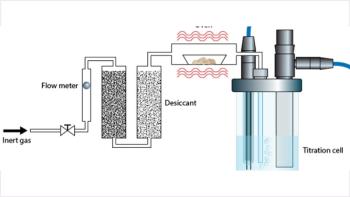
Both the MMLLE and SLM techniques can be interfaced directly to LC. The work of Sandahl and co-authors showed that a combination of the two membrane methods provided extraction conditions that allowed the determination of charged, ionizable and non-polar compounds at the sub-parts-per-billion level with precision in the neighbourhood of 5%.24 The experimental set-up used in their experiment is depicted in Figure 3. Syringe pumps were used to control the flowing steams and allowed more precise control than the peristaltic pumps used earlier. Membranes were mounted in machined blocks described earlier.20 The solvent n-octanol was the optimum acceptor in MMLLE because about 30 μL could be injected into the reversed-phase HPLC column without causing excessive band broadening. In SLM, up to 250 μL of extracted analyte in 0.015 M sulphuric acid could be accommodated.
Figure 3: Set-up for MMLLE and SLM. (Reprinted by permission of Elsevier Scientific Publishers from reference 24.)
Solid-Supported LLE
Instead of using a separatory funnel to perform LLE, one can immobilize one liquid phase in an inert medium packed into a polypropylene tube and percolate the other immiscible liquid phase through the immobilized liquid in a manner similar to chromatography (Figure 4). The most frequently used inert material is a high-purity diatomaceous earth with a high surface area and high capacity for aqueous adsorption. The process is termed solid-supported LLE or supported liquid extraction (SLE), and is a popular alternative to the classic LLE experiment. In practice, the aqueous phase, which could be diluted plasma, urine or even milk, is coated onto the diatomaceous earth and allowed to disperse for a period of time, usually a few minutes. The aqueous sample spreads over the hydrophilic surface of the diatomaceous earth in a very thin layer. Next, the immiscible organic solvent is added to the top of the tube and comes in contact with the aqueous layer finely dispersed over the high surface area packing. Rapid extraction of analyte occurs during this intimate contact between the two immiscible phases. The solvent moves through the packing by gravity flow or by use of a gentle vacuum.
Figure 4: Steps in supported liquidâliquid extraction. (Courtesy of Biotage, Charlottesville, Virginia, USA.)
The tubes used in SLE resemble SPE tubes, and their volumes can range from 0.3 to 300 mL. Some suppliers provide prebuffered pH 4.5 and 9.0 cartridges for extracting acidic and basic substances, respectively. For example, at low pH, acids will be in their unionized form and, thus, will be extractable from the immobilized aqueous phase. At high pH, amines will be in their neutral form and thereby can be extracted into the organic phase. It is possible to add salt to the aqueous sample so that a "salting out" effect occurs thereby leading to better extraction efficiency of certain analytes. The SLE tubes can also be used to remove small amounts of water from organic samples.
Because there is no vigorous shaking as in conventional LLE, there is no possibility of emulsion formation. Because the packed tubes are considered disposable, there is no glassware to be cleaned after use. The entire process is amenable to automation, and packed 96-well plates with several hundred milligrams of packing are readily available to perform this task. The 96-well plates are suitable for extraction of 150–200 μL of aqueous sample and, thus, miniaturize the conventional LLE experiment as well.
Conclusion
The time-tested technique of LLE is still among the most widely used of all extraction methods. However, the move towards miniaturization has resulted in improved techniques that use vastly smaller amounts of organic solvent, provide superior extraction efficiencies, permit the on-line coupling to analytical measurement techniques, and allow easier automation and higher extraction throughput.
Ronald E. Majors is business development manager, Consumables and Accessories Business Unit, Agilent Technologies, Wilmington, Delaware, USA and is a member of the editorial advisory board of LCGC Europe. Direct correspondence about this column to LCGC Europe, Advanstar House, Park West, Sealand Road, Chester CH1 4RN, UK, e-mail:
References
1. R.E. Majors, LCGC N. Am., 20(11), 1098–1113 (2002).
2. R.E. Majors, LCGC N. Am., 14(11), 936–943 (1996).
3. E. Baltussenet al., J. Microcolumn, 11(10), 737 (1999).
4. J.C. Wu et al., J. Chromatogr. A, 976(1–2), 357–367 (2002).
5. C.L. Arthur and J. Pawliszyn, Anal. Chem., 62, 2145 (1990).
6. M.A. Jeannot and F.F. Cantwell, Anal. Chem., 68, 2236–2240 (1996).
7. S. Liu and P.K. Dasgupta, Anal.Chem., 67, 2042–2049 (1995).
8. D.C. Wood, J.M. Miller and I. Christ, LCGC N. Am., 22(6), 516–522 (2004).
9. M.A. Jeannot and F.F. Cantwell, Anal. Chem., 69, 235–239 (1997).
10. Y. He and H.K. Lee, Anal. Chem., 69, 4634–4640 (1997).
11. B. Buszewski and T. Ligor, LCGC Europe, 15(2), 92–97 (2002).
12. E. Psillakis and N. Kalogerakis, J. Chromatogr. A, 938(1–2), 113–120 (2001).
13. E.M. Gioti et al., J. Chromatogr. A, 1093, 1–10 (2005).
14. W. Welter and B. Neidhart, Fresenius J. Anal Chem., 357, 345–350 (1997).
15. S. Santesson et al., Anal. Chem., 76, 3030–3038 (2004).
16. S. Santesson and S. Nilsson, Anal. Bioanal. Chem., 378, 1704–1709 (2004).
17. S. Santesson et al., Am. Lab., 33(3), 13–18 (2001).
18. B. Karlberg and S. Thelander, Anal. Chim. Acta, 98, 1–7 (1978).
19. J.A. Jonsson in Sampling and Sample Preparation for Field and Laboratory, J. Pawliszyn, Ed. (Elsevier Science, Amsterdam, 2002) pp. 503–530.
20. J.A. Jonsson and L. Mathiasson, LCGC N. Am., 21(5), 424–438 (2003).
21. L. Zhu, L. Zhu, and H.K. Lee, J. Chromatogr. A, 924, 407 (2001).
22. T. Hyötyläinen et al., J. Chromatogr. A, 1956, 267–271 (2004).
23. K. Kuosmanen et al., Anal. Bioanal. Chem., 375(3), 389–399 (2003).
24. M. Sandahl, L. Mathiasson, and J.A. Jonsson, J. Chromatogr. A, 893, 123–131 (2000).
Articles in this issue
over 20 years ago
It's Going to Breakover 20 years ago
Chromatography for Bioanalytical Chemistsover 20 years ago
New Technologiesover 20 years ago
Acquisition adds immunoaffinity columns to Waters' portfolioAdvertisement


Advertisement
Advertisement
Trending on LCGC International
1
HPLC, PTR-ToF-MS Enable AI Grading of White Tea
2
Py-GC–MS Reveals Microplastics in Playgrounds
3
Analytical Procedure Lifecycle Approaches in Accordance With ICH Q14 and ICH Q2(R2): Opportunity Knocks or Just Another Challenge and Headache? (Part 2)
4
LC-MS/MS Links Vitamin D Levels to Sleep Timing
5